Kirchhain Adaptor Frames
Bee Breeding
Wohlgemuth Introduction Frame
|
|
|
|---|
|
Kirchhain Adaptor Frames Bee Breeding Wohlgemuth Introduction Frame |
Frames
|
|---|
I use the word frames quite loosely here as most of the Kirchhain frames are just top bars, but some developed by Peter Springall have wire rims and some others have wooden dowels to stiffen the sloping sides. This latter type was developed by myself, when I used the plywood forerunner of the Kirchhain nuc, because I found that the row of cells that were immediately below the wooden top bar were often left empty by the bees, which made this line of cells very weak and prone to break of if there was any weight in the bulk of the comb.
|
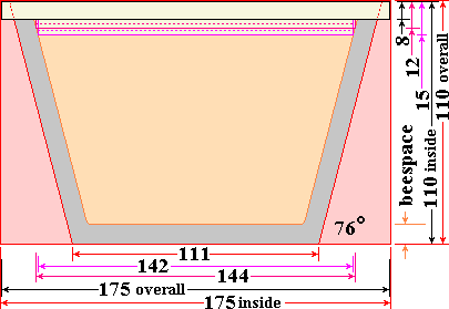
This drawing shows the dimensions of a Kirchhain frame and the space that it occupies. The three types of top bar that are depicted by the coloured outlines are illustrated in the drawings below. I used a drawing similar to this to devise the layout of the large frames that will fit into a B.S. National hive. |
|
|---|

The plain topbar is often supplied without the central groove, that can be used for starter strips or just a bead of melted beeswax. If grooves are desired it is fairly important that they are cut in a 'blind' fashion otherwise the comb can be joined to the top of the sloping sides of the box. The lug recesses that the bars are located in are 10 mm deep and so bars of up to that thickness can be used.

Using the stepped form shown here the setting up for the grooving is simplified, but the notches need to be cut in a separate operation.

The form with the scalloped recesses is sometimes supplied as standard with the nucs and has the benefit of being easier to remove if you have thick stubby fingers and the gap that occurs between adjacent recesses is a useful place to put a queencell.
|
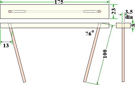
This is the frame that I developed to overcome the floppy comb breaking off.
|
|---|
The 100 mm rods had their tips dipped in pva glue and were forced into place so that the end was flush with rim of the hole at the point nearest the end of the top bar. After the glue had dried the slight protrusions were sliced off crisply, using a very sharp curved knife blade and then a quick touch on a belt linnisher, did the final smoothing.
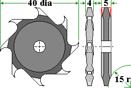 The grooves that are faintly outlined in grey were also made
with a special cutter, which was developed so that the starter strips
required less molten beeswax to fix them in position. This cutter
started life as one that would cut a plain 5 mm wide groove...
The cross section of it's original form is shown at extreme right. To
modify it I mounted it on a spindle, placed it in the chuck of a
lathe and fitted a die grinder onto the lathe slide. The 30 mm grinding
wheel was spun at 10,000 rpm and gradually traversed into contact with
the spinning cutter. The tip width was reduced to 2 mm and as a
result of removing the material the cutter ended up 4 mm wide at
it's maximum thickness and of the profile shown in the inner right
view. For ease of drawing the cutter is shown with eight teeth, but
the actual cutter has nine teeth, spaced at 40° intervals.
Grooves for fitting foundation normally have a 3 mm width... Using this cutter the bottom of the groove is 2 mm wide, but the sides of the groove flare outwards. The groove has a wider effective width the deeper that it is cut. This means that you can set it to produce a shallow groove 2 mm wide or if you require a groove 3 mm deep then the mouth of the groove is 3 mm wide, because of the progressive curvature of the sides of the groove, foundation is easily deformed into the narrower bottom of the groove which then requires less liquid wax to fix it in place.
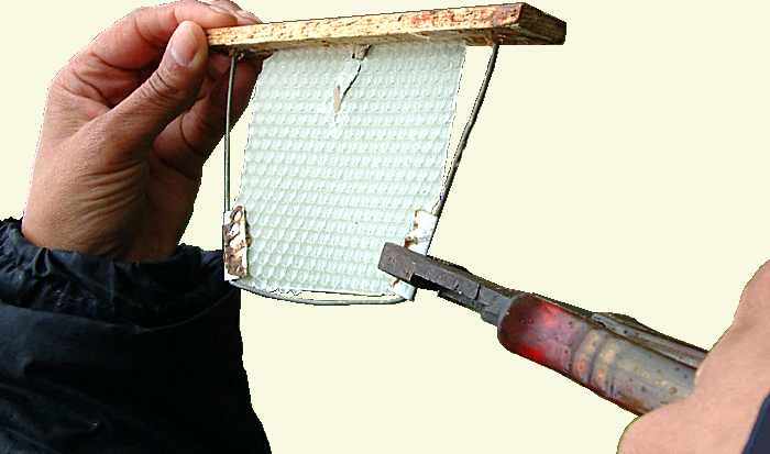
Peter Springall's version uses wire to form a rim and small tabs of tinplate folded over and crimped with pliers to trap the foundation. This keeps the midrib of the comb under control while the comb is being drawn, the tinplate and wire become incorporated during comb drawing.
John Perkins' Method using plastic foundation.
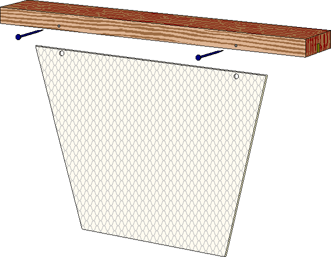
 John's method uses plastic foundation to provide a rigid base for the otherwise
unsupported comb. The drawings are self explanatory and have been copied from John's originals
with his permission. He used to just glue the plastic foundation into the groove, but now he takes the
'belt and braces' approach. He uses a small
Dremel type drill to pre-drill into one side
of the top bar and through the plastic foundation. The gimp pins then fix and hold in the other
side of the top bar. This may sound complicated, but you can do them very quickly
when you have had a little practice, the gimp pins
hold everything in place while the glue dries.
The whole assembly is very secure, once the glue has set, and you can manipulate them in any direction with the confidence that they are not going to fall apart or bend.
The plastic foundation can be cut to size and shape using a template.
Originated... February 2003, Revised... 10 March 2003, Upgraded... 23 May 2005, Amended... 23 December 2005, Addition... 21 November 2006, Addition... 10 December 2006,
|