Small coils of nichrome wire (NiCr)are best as the coil will last for a long time before failing. Stainless steel wire intended for reinforcing wax foundation can be used, but it is less durable and requires more turns to generate enough heat.

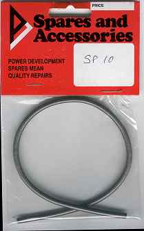
NiCrome (nichrome) Wire can be obtained by purchasing a "heating spiral" from an electrical contractor, the one illustrated at right is rated at 1 KW (on a 230v supply) and cost £3.99 in 2001. It is in the form of a tightly wound spiral shown in the inset at left.

Before we can make use of it it requires to be straightened... It is tough stuff, but this can be achieved by placing one end in a vice and by pulling and curling using a round hardwood dowel and industrial gloves. This removes the waviness from the original spiral and the curved shape that results will not hinder the rest of the process.


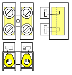
The connections to the coil can be made via a "chocolate block" connector (the white one). This is so called as they are usually supplied as a strip of twelve and can be cut to length simply with a knife. The near right version is made of hard thermosetting plastic that can be parted using a hacksaw and this type is more resistant to the high temperatures that we will encounter.
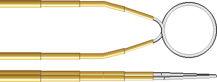
One of the reasons that this type of coil fails is that the lead or support wires get red hot as well as the part of the coil that encircles the glass tube. Thin brass tubing (available from model shops) can be threaded on to the coil leads for rigidity and to concentrate the heat within the coil itself.

The illustration shows (at 2.5x) four diameters of brass tubing that fit exactly one inside the other, the bore of the innermost of these is a good fit for the NiCrome wire which is inserted into the smallest tube. The brass tubes also stop the screws in the connector from cutting through the wire and they provide physical support for
the active part of the coil. They also provide a heat sink path to allow the heat in the lead wires to be dissipated. The tubes can be coated in solder cream before assembly, although soft solder will not take very well to the NiCrome wire... The soldering of the brass tubes increases the final rigidity and stops oxidation occurring between the concentric layers of brass. Soldering also reduces the impedance of the brass tubes and also to a certain extent this reduced impedance is passed on to the lead wires themselves by the fact of close physical contact between the surface of the NiCrome wire and the inside surface of the innermost tube.
The NiCrome wire needs about 4 amps flowing to get red hot, but the voltage will only be in the one volt region for a single turn coil (I describe on a separate page the making of
a suitable transformer)
multiple turn coils of thinner wire can be heated from a 12 volt battery, or a battery charger, or battery under charge.
The form of the coil affects the shape of the finished tip. The number of turns, the overall diameter, arrangement of turns all have an effect. In addition, tubular shields can be positioned coaxially between glass tube and coil so as to mask some of the heat from the glass.

Single turn coil with brass tube support wires that are arranged at the same spacing as the pitch of the electrical connectors. The coil illustrated is about 8 mm ID.
Additional electrical connectors fitted to extended brass tubes can also be used as a 'plug and socket' arrangement for interchanging the coils, with the added rigidity helping to preserve the coils which tend to become brittle with use.


