Morphometry
|
|
|
|---|
|
Morphometry |
Morphometry Tools For Use With Honey Bees |
|---|
Many measurements of body parts have to be made repeatedly on large numbers of bees. These can be taken in a simple way with the aid of specific tools.
|
This has it's own built in measuring wire. This particular version was made with materials that were to hand and is a little more robust than others I have seen. There are several parts... The eyeglass itself was made of Bakelite and had a 100 mm focal length, the electrical connector came from my junk box and the copper wire was a strand pulled from some thick cable I had lying around.
|
|
A series of 1 mm diameter holes was drilled in the side of the body (note the stagger in the bottom row of holes). The end of some 1 mm copper wire was soldered to the brass connector and the wire fed through the holes, soldering each time the wire passed over the front of the brass block. Even pulling the wire tight each time, the result was still a little loose so a dollop of superglue was used to firm everything up. |
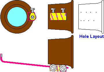
|
|---|
|
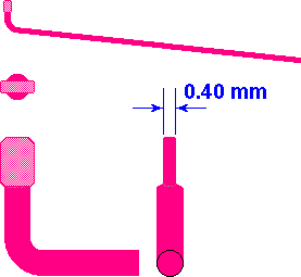
The gauge wire shown in the illustration at right is fitted into the bore of the connector and the screws tightened to hold the wire so that the flattened measuring tip is in focus when viewed through the lens. The enlarged view shows how the wire is flattened at the end. The flattening is achieved using a pair of pliers, not the jaws themselves, but the root nearest the pivot so that adequate leverage is obtained. The tab so formed is measured using a micrometer and the squeezing repeated until the tip is exactly 0.40 mm thick. Note... Plenty of illumination is required for this job. |
|
|---|
There are two modifications that I will perform some time in the future:-
The first is to fit another connector on the opposite side the eyeglass body so that a second wire can be fitted to act as a stop so that my thumb is in a repeatable position.
The spring, removed from an old alarm clock will be my second modification and this will be fitted so that the curl of the spring holds the eyeglass in place in my eye socket (I have seen jewelers use this method in the past).
A further possible modification may be helpful in future to correct for the astigmatic component of my eyesight defects... This would entail cutting a circular portion from an old plastic spectacle lens and gluing it inside the body of the eyeglass.
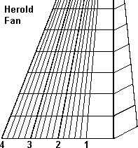
Herold fanThis enables rapid assessment of Cubital index using the 35 mm slide projection method. This may look complex at first sight, but it is in fact quite easy once you have done two or three. When using the projector ensure that the axis of the lens is exactly perpendicular to the wall both horizontally and vertically. |
|
|---|
|
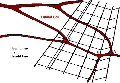
The Herold Fan is held flat on the wall so that vein "AB" is parallel to the "rungs" of the right hand ladder. The extreme right side of this "ladder" should pass through the centre of point "A". The line that forms the left of this "ladder" should pass through point "B". The line that then passes through point "C" then represents the Cubital Index. Joint "C" is a broad triangle, the actual measuring point should be the centroid of this triangle. I had some difficulty drawing the full sized versions of the Herold fan... There were some minor errors in the original printed sheet that I have. I have corrected these and provided both left and right hand versions which can be printed via your browser. There are still some minor errors, but they are very small (less than 0.17 mm). I have used colour to aid those that are, like me, challenged in the eyesight department. |
|
|---|
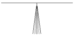
Discoidal cardCan be used with the projection method for discoidal shift measurement. (click on small image at right for full size printable version) |
|
|---|
Editor's Note... This design is likely to change in the light of some old information that has been uncovered and some ongoing research in Ireland.
Glossameter is the technical term for the device that measures tongue length (or more precisely tongue reach). Versions of this page prior to March 2006, had the spelling as glossimeter, but having discovered that there is a device of that name that is used for measuring the 'glossiness' of a painted surface, I have adopted the term glossameter (which is more accurate anyway).
|
This version is simply made from acrylic sheet (Perspex, Plexiglass) a thickness of 3 mm is ideal. A high degree of accuracy is required in the marking out, so if you cannot manage this, it may be prudent to have the device(s) made by an industrial engraving company. |

|
|---|
The illustration below shows the central portion at higher magnification. The diagonal scale is used in order to achieve extra accuracy in reading the results. Three readings can be taken using the 31 drillings shown. The principle can be extended to a larger number of drillings for even more information gathering, or more than one device can be used, in the hive being tested, at the same time.
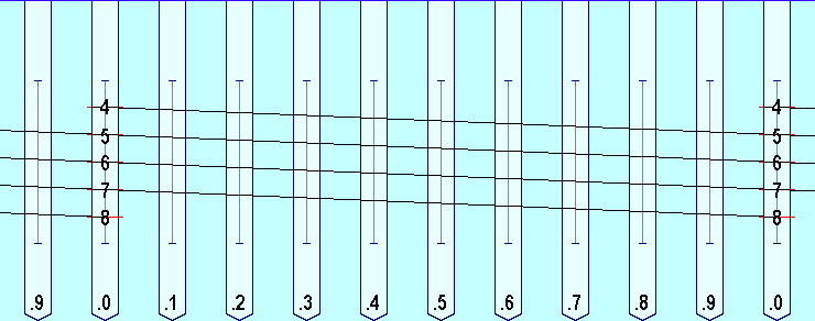
We make the device as follows... Using a drill press and positioning jig, the holes are drilled into the edge of the plastic sheet, a diameter of 1.1 mm or 1.2 mm is suitable, even up to 1.6 mm, (depending on the availability of drill bits), but do not forget that the width of the entrance is a limiting feature, as the wider the hole is the further a bee's mouth parts can enter into the mouth of the drilling. Differences in hole diameters between differently made devices will need further cross calibration before the data from each can be used in a wider study. The depth of each hole needs to be more than any possible tongue length and in the case illustrated is 10.5 mm and is set using the depth stop on the drill press. The pitch of the holes in my example is 2.54 mm (1/10") see flour Dredger, but a pitch of 2.5 mm is appropriate if marking out rather than using a jig. After drilling, the bores can be polished using wooden toothpicks shaved down and applied with a copper or chrome cleaning abrasive agent, then placed in the chuck of a Dremel type tool. The top surface can be polished flat using 'wet and dry' abrasive paper lubricated with household soap and water.
Marking out the calibration lines requires attention to detail, a straight edge, freshly sharpened scriber and a scalpel along with high quality steel rule.
To use the glossameter device all the drillings are filled with honey, this can be achieved using a 19 gauge hypodermic syringe needle with the needle tip ground off (again using the Dremel tool) and a 5 ml or 10 ml syringe. The glossameter is introduced into the hive at a reasonably level angle and left long enough so that all the remaining honey is of the same depth.
It should be stressed that this does not measure tongue length, but that the parameter being measured is the reach of the bees with the longest tongues. Such a measurement cannot be used directly to compare to a morphometric database, but is an excellent method of making comparisons between colonies. It must also be stressed that the distribution of tongue reach within a colony of bees will be the summation of the bell shaped distribution curves that are due to all of the patrilines expressed within the colony and as a result the longest tongue reach may only occur in a very small percentage of the bees concerned.
Note... Syringe needles are sized according to the Stubs' wire gauge, this is an alternative name for the Birmingham Wire Gauge (BWG) that occurs on the conversion chart.
Dave Cushman.
Page created Autumn 2000
Page updated 07/12/2022
Written... Autumn 2000, Upgraded... 22 March 2006, Note added... 13 May 2006,
|