| "E" Home |
|---|
| Prev. Menu |
|---|
RS Components
Wire Gauge Chart
|
ELECTRONICS "A-Z" INDEX |
|---|
| Back |
|---|
|
|
RS Components Wire Gauge Chart |
ETD Series Ferrite Cores |
|---|
|
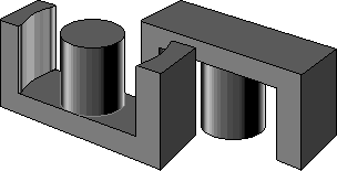
I have used this style of core, in a few applications,
mainly in inverter type power supplies as the power transformer (at about 40 kHz chop frequency).
Generally the mating surfaces are ground flat for minimum reluctance, but some types have deliberately shorter central limbs in order to provide a central air gap... This increases the reluctance, but improves the tolerance on the reluctance. |

|
|---|
 |
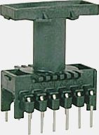
The moulded bobbin shown here fits the centre limb
that occurs when a pair of cores are placed face to face. The pins
are arranged as 'dual in line'.
This particular one is Part Number: FD9630 from
MILES - PLATTS Ltd.
The version illustrated at left has vertical core orientation, but other types exist where the core is held horizontally, usually the distance between the rows of pins is greater for the horizontal type. |
|---|
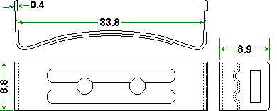
| The completed assembly is held together by spring steel clips of the shape indicated at right, the dimensions are those that apply to an ETD29 clip that latches on to small lugs moulded into the bobbin. Two are required. |

|
|---|

|
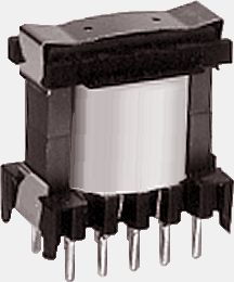
A finished transformer is shown in this picture. Note that it has a
different style of clip to the one illustrated above, such variations occur
between different manufacturers.
The examples quoted throughout the rest of this page are those of the particular versions offered by RS Components They are a supplier that is local to where I live and their website has been provided some of the information given here. If you use components from a different supplier then you must use the design parameters published by your supplier rather than any figures quoted here. |
|---|
| Size Designation | Para meter | ETD 29 | ETD 34 | ETD 39 | |||||||||
|---|---|---|---|---|---|---|---|---|---|---|---|---|---|
| Core Material | F47 | F44 | F5 | F5A | F47 | F44 | F5 | F5A | F47 | F44 | F5 | F5A | |
| Inductance factor (nH/turns2) | AL | 1800 | 1950 | 2000 | 2350 | 2150 | 2250 | 2400 | 2480 | 2440 | 2470 | 2700 | 3120 |
| Permeability (effective) | µe | 1332 | 1443 | 1480 | 1740 | 1385 | 1450 | 1550 | 1600 | 1435 | 1455 | 1590 | 1835 |
| Path length (effective) | mm | 70.4 | 70.4 | 70.4 | 70.4 | 78.6 | 78.6 | 78.6 | 78.6 | 92.2 | 92.2 | 92.2 | 92.2 |
| Path area (effective) | mm2 | 76.0 | 76.0 | 76.0 | 76.0 | 97.1 | 97.1 | 97.1 | 97.1 | 125 | 125 | 125 | 125 |
| Winding area (single section bobbin) | mm2 | 89 | 89 | 89 | 89 | 123 | 123 | 123 | 123 | 177 | 177 | 177 | 177 |
| Size Designation | Para meter | ETD 29 | ETD 34 | ETD 39 | |||||||||
|---|---|---|---|---|---|---|---|---|---|---|---|---|---|
| Inductance factor (nH/turns2) | AL | 1800 | 1950 | 2000 | 2350 | 2150 | 2250 | 2400 | 2480 | 2440 | 2470 | 2700 | 3120 |
| Centre limb gap | mm | 0.1 | 0.2 | 0.5 | 1.0 | 0.1 | 0.2 | 0.5 | 1.0 | 0.1 | 0.2 | 0.5 | 1.0 |
| Core Material | F44 | F44 | F44 | F44 | F44 | F44 | F44 | F44 | F44 | F44 | F44 | F44 | |
| Permeability (effective) | µe | 590 | 340 | 160 | 92 | 645 | 375 | 175 | 100 | 735 | 425 | 205 | 120 |
| Path length (effective) | mm | 70.4 | 70.4 | 70.4 | 70.4 | 78.6 | 78.6 | 78.6 | 78.6 | 92.2 | 92.2 | 92.2 | 92.2 |
| Path area (effective) | mm2 | 76.0 | 76.0 | 76.0 | 76.0 | 97.1 | 97.1 | 97.1 | 97.1 | 125 | 125 | 125 | 125 |
| Winding area (single section bobbin) | mm2 | 89 | 89 | 89 | 89 | 123 | 123 | 123 | 123 | 177 | 177 | 177 | 177 |
Written... 26 April 2002, New Domain 20 April 2004, |