|
|
|
|
|---|
|
|
GB3LE 70 centimetre repeater Hexalators |
|---|
Hexalator is a trade name of TDK, for a type of circulator composed of microwave ferrites, mesh like centre conductors and magnets.
The first hexalator... I am not sure of the date, but I remember the occasion! Jack Bennett G3PVG announced that he had obtained the device, while several of us were on our morning trip to work (in QSO, probably on S0). It obviously made a big impression on me, as I can even remember the exact piece of road that I was driving along at the time.
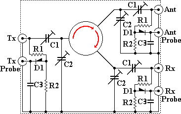
The second hexalator was built by myself, from parts provided, or paid for, by LRG. In essence it was a die cast box with three "N" type connectors for the signal cables and three BNC type connectors for resistive, filtered diode probes that were permanently connected to the main signal lines. This method gives good stability as making test connections has little or no effect on the impedance of the signal lines themselves. The connections from the Hexalator to the trimmers and the "N" type connectors were by means of double sided PCB microstriplines sized and shaped to suit the expected impedances at every point in the system. Finally each of the three identical sections were screened from each other by pieces of double sided pcb material soldered up to form enclosing boxes with holes to allow for trimming tool insertion. Captive dust caps were provided to cover the BNCs when they were not in use.
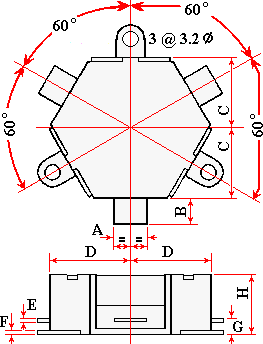
Hexalator dimensions
|
All dimensions in mm . The connection tab thickness seemed to be thinner, and the tab shorter, than the table indicates. The TDK specification sheet shows the upper limit of the CU 322A as 400 MHz... The actual device used had been specially selected, by testing from a production batch, for use at 432 MHz. |

|
|---|
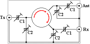
Schematic of the original unit

|
Circulator = CU 331A |
Isolation greater than 20 db |
|---|
Schematic of the completed new unit for MK2.

|
Circulator = CU 322A The parts list has not been completed, as the details were passed to the next GB3LE project engineer... From memory, I reckon C1 and C2 were 4 - 10 pf, R1 and R2 were 51 R and the diodes were 1N 918. I hope these details will come to light later. |
|---|
PCB dimensions
I have the drilling jig that I made for the PCB, but cannot find it at present.

Physical appearance of MK2 hexalator
At some point the cavities were replaced by a 'block filter'. I do not think this required an aerial circulator.
My memory is far from perfect, corrections and additional details are welcome and are actively sought.
|
|
|
|
|
|
|---|