Measurement of wing vein characteristics to establish race and breeding purity in honey bees, with the intention of using the data for breeding selection purposes.
These measurements can be taken using a 35 mm slide projector to project the images of mounted wings onto a white wall. It is important that the projector is arranged so that the beam is aligned perpendicular to the wall in both the horizontal and vertical planes, otherwise optical distortion will degrade the accuracy of results. (This usually means mounting the projector at a greater height than a normal projector stand.)
Several computer programs have now been prepared so that the slides will go into a 35 mm slide adaptor on a high quality document scanner or purpose designed slide scanner. Enabling the images to be read and the results printed out automatically. There is a LINUX version available on the
Linux Downloads page. Any
other Open Source software for beekeeping measurements will also be provided as it is released.
A description of how to prepare and mount the wings is given in a page titled
Wing Mounting.

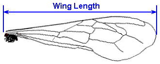
The maximum possible distance should be measured for consistency.
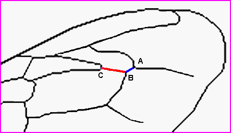
Cubital Index... We can measure the ratio of two of the wing vein segments to obtain this:-


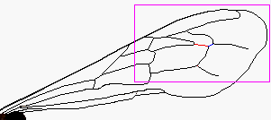
The enlarged drawing at right is of the purple rectangle shown on the smaller overall sketch above.
The points A, B & C should be judged to the centroid of the vein junctions concerned. The distance
"BC" is divided by the distance "AB". There is a tool for doing this known as the Herold Fan named
after Pfarrer Herold who devised the method.
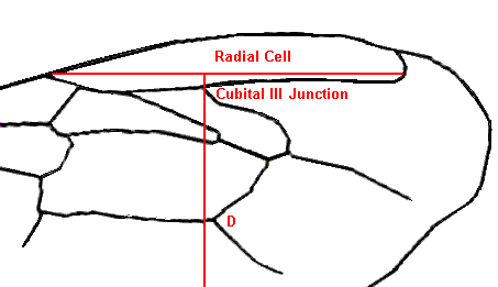
Discoidal Shift... Is used most when dealing with Amm types as most other types are zero or positive whilst for Amm this is a negative value.

The measuring tool (known as a discoidal card) is set so that the horizontal line passes through the extreme tips of the radial cell with the perpendicular passing through the junction of the "Cubital III Cell" and the "Radial Cell". The offset of point "D" is measured using the angular gradations on the tool. The particular example shown here is a positive value. Judgement of points can be the cause of discrepancies in information generated by different operatives.
Much of the calculation work has now been taken over by computer application packages, but as measurement becomes more easy and precise, it calls into question the accuracy of the databases that are used for comparison standards. Database refinement will be the subject of a future page.


