"E" Home
Prev. Menu

Drop Machine
Similar Transformer Project
ELECTRONICS
"A-Z" INDEX
Back
G8MZY logo

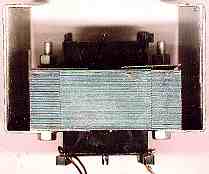
Electrical Transformer for Drop Machine

For those that are competent in electrical engineering I will describe the process of converting an existing, ready made, transformer into one that can provide power, in incremental steps of around one sixth of a volt, to the low voltage heating coil in the drop machine.

Safety is important... If you are not confident or competent to carry out this work, then please consult someone who is! A trained electrical engineer will be able to follow the directions on this page to produce the article required.

If you do not already understand transformer theory you should be able to find the information on the web, an overview is given on Transformers.

Design considerationsThe heating coils in the drop machine are small and will require low voltages. Different coils will require different voltages, but coils with lead wires encased in brass tubing will require even lower voltages due to the relatively low lead impedance. The finished transformer will be required to deliver four or five amps, but the duty involved is low, only a few minutes in any hour. The processes that are required to re-calculate the turns and gauge of wire are also covered in another project, and reading that may help your understanding of this one.
Transformer for Drop Machine

Choosing a suitable transformer to modify was easy, I had an 18 VA unit available and had already modified an identical one for another purpose. Five amps at a few volts will not tax the conservatively rated version I had, anything with a nominal rating between 20 VA and 60 VA should be satisfactory. Two views of the original are provided at right. Original Transformer side view
Original Transformer


Initial testing should be carried out to give us useful information later. Using a temporary, but safe method, ( I use the test lead shown below, It is very short as I have a row of socket outlets along the back of my workbench. ). Test lead
Connect the primary to a source that is of the correct rated voltage and measure both the primary voltage and the secondary voltage. Record both details on a sheet of paper. Leave the transformer running at no load for 15 minutes, disconnect from the supply and then feel the device to see if it is hot. 15 minutes should be enough to cause smoke and extreme temperature if shorted turns are present.

Disassembly... take out any screws that hold the device together and remove any clamps or terminal blocks, making note of the colours and origin of all wires (on our sheet of paper). Remove the laminations one by one taking care not to damage any of them (the first one may be very difficult to remove). The secondary coil must now be removed, counting every turn of wire as you do so, record the number of turns on the paper. In the case of my particular transformer there were 72 turns and the voltage recorded was 13.2v (primary was a nominal 240v and the measured voltage on the primary was 242v.

Bobbin with Secondary removed 
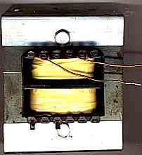
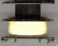
The bobbin will look something like this, once the secondary turns have been removed.

If your secondary winding has many turns of thin wire... there is another way of doing this without counting the turns. Strip off the secondary winding, clean up the bobbin and rewind 50 turns of wire in place of the original winding secure this in place with sticky tape and then reassemble the core, interleaving the laminations and finally place on a solid flat surface and very gently tap the "E"s and "I"s into solid contact with each other. having rebuilt the transformer with a 50 turn secondary, use the temporary test lead, connect the primary to a source that is of the correct rated voltage and measure both the primary voltage and the secondary voltage. Record both details on our sheet of paper.

Either of the two above methods will give us a "no load" turns per volt ratio which we have to correct for use at full load... Transformers around this size have a full load regulation in the 10% region and so for my particular transformer we have 72 turns and 13.2v - 10% = 11.9v... Which is near enough to six turns per volt.

Recalculating for our desired output
Six turns per volt can be expressed as one sixth of a volt per turn.
grouping of turns for maximum flexibility
I had 10 terminals in my strip and I wanted the maximum possible number of variations of voltage... As one single turn would be about one sixth of a volt, I opted for a scheme that gave me a maximum voltage of 11 volts with 66 combinations giving increments of one sixth of a volt.

The different voltages are obtained by selecting the appropriate terminals and using one two or three windings in series. Terminals 1 to 5 will give 1, 2, 3, 4, 5, 6, or 7 turns depending on which terminals you use. Terminals 6, 7 and 8 give either 8, 16 or 24 turns and there are 33 turns available between terminals 9 and 10.

The maximum current demand is when heating elements of relatively thick resistive wire are used so the transformer turns that will produce the lowest voltages will be wound with the thickest wire to keep losses low and the 33 turn winding will be somewhat thinner as higher impedance heating coils will draw less current than the low impedance ones. This makes better use of the available window space (there was about 20% spare window space when it was used as a bar lighting device).

It should be noted that the actual voltage per turn in other home made examples will be different, but the principles still apply.

Rewinding the secondary... Normally I would wind the secondary with the highest current loading first so that there would be less 'resistive' copper losses in the low voltage winding. This case is different as we have two lead wires and three tappings in the first seven turns. Winding these first would make winding the rest of the secondaries messy and so I will wind the 33 turn winding first as it is of the thinnest gauge of wire (I will use the original 1.05 mm diameter wire for this coil and the 24 turn section of the next winding).

The wire that was removed was wound on to a piece of wood that had been padded with corrugated cardboard, although in good condition, it was kinked due to the original bobbin being square. If we tried re-using this, it would not go back very tidily and we would lose window space. Before it is re-used it needs to be straightened... First clamp one end of the wire to a suitable fixed object using a "G" clamp ("C" cramp?) and a couple of pads of scrap timber. Then unroll some of the wire and stretch it taught, at the point that it is just about to stretch give a small extra tug which will elongate the wire by about 1%... This will straighten this portion of wire sufficiently to wind the first layer of turns, but will not damage the adhesion of the varnish to the wire.

The 33 turn winding was completed and notes made of starting and finishing points. A piece of double sided adhesive tape was wrapped for one complete turn around the 33 turn section and then the eight turn and sixteen turn windings were made, again recording start and finish points. Another layer of double sided tape was placed over this. I found some wire of 1.6 mm diameter and wound seven turns around the part finished bobbin, whilst this temporary coil was in place the tapping points were marked on the wire with a felt tipped pen. The temporary coil was then removed so that the taps could be soldered in place.

Terminating the thick winding

Re-coring

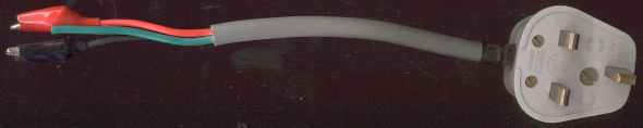
Terminating the conductors

Terminals and right angle stiff wires
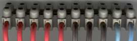
I had available some off cuts of 4 mm2 solid single core cable and I fitted 100 mm lengths of this into each way of my terminal block. I then used a 6 mm diameter steel rod as a former to bend each wire at right angles, so that they would fit through a row of suitably spaced holes in the front plate of the enclosure.


Drop Transformer Schematic diagram


Testing the unit


Fuses and fuse Ratings


Final tweaks


Electrical interference (EMC)


Disclaimer!
I am a qualified electrical and electronic engineer and as such I take precautions to ensure my own safety and the safety of others. I cannot be held responsible for the work of others that are not under my direct supervision.

"E" Home
Prev. Menu
Back
Top
Email Me!

Written... 13 October 2001, Revised... 18 December 2001, Revised... 28 February 2002, New Domain... 06 April 2004,

Electronics Favicon Coding Standard 2003 Issue 5